creo sheet metal process Creo Elements/Direct Sheet Metal creates a new 3D sheet metal part. Options . Metal Fabrication; Commercial & Residential HVAC Ductwork Fabrication; CNC Plasma Cutting Services; Heavy Gauge Plate Shearing; Precision Metal Punching; . YANKEE SHEET METAL. 35 WROBEL PLACE. EAST HARTFORD, CT 06108 (860) 528 – 9431. First Name (required) Last Name (required) Email (required) Telephone (required)
0 · sheet metal in creo parametric
1 · sheet metal design in creo
2 · creo sheet metal tutorial pdf
3 · creo sheet metal tutorial
4 · creo sheet metal roll bend
5 · creo sheet metal basics
6 · creo parametric sheet metal tutorial
7 · creo convert to sheet metal
Shop now Shimano XTR SC-M9051 Di2 Digital Display Unit, Junction Box with 3 E-Tube Ports and Charging Port at Ben's Cycle. Buy online the best.
A sheet metal manufacturing process consists of the following basic steps: 1. Set up the manufacturing database. It may contain such items as workcells (machine tools) available, tooling, site parameters, etc.Creo Elements/Direct Sheet Metal creates a new 3D sheet metal part. Options .
You can create sheet metal parts in one of the following ways: • Sheetmetal .

Creo Elements/Direct Sheet Metal creates a new 3D sheet metal part. Options specific to Solid include: • Cut replaces an existing bend edge by a cut edge and divides the selected part into two parts.You can create sheet metal parts in one of the following ways: • Sheetmetal Mode—Using a specialized sheet metal environment • Assembly Mode—Using a top-down approach.
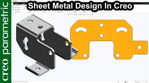
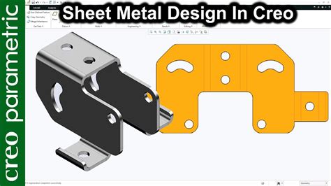
In this tutorial, you will learn a step-by-step approach to designing a sheet metal part in Creo Parametric. The tutorial covers the planar wall, extrude wall, flat wall, and flange wall. This Video explains basic sheet metal modeling in creo. Process of creating the basic features of sheet metal like bend, flange, cut, punch, wall creating, b.
sheet metal in creo parametric
Check out this video on Creo Sheetmetal Design from PTC Application Engineers. Presenters: Lino Tozzi (Technical Specialist, Fellow) and Ryan Butcher (Technical Specialist, .

By enabling the sheet metal mode in Creo, you've essentially entered a specialized design environment tailored to the unique demands of sheet metal components. This mode equips you with the tools and capabilities .1: Introduction to the Creo Parametric Sheetmetal Design Process. 2: Sheetmetal Model Fundamentals. 3: Creating Primary Sheetmetal Wall Features. 4: Creating Secondary .
Sheetmetal Design using Creo Parametric is a comprehensive training course that teaches you how to create sheet-metal parts in Creo Parametric. The course builds upon the basic lessons you learned in Introduction to Creo Parametric .
Creo Elements/Direct Sheet Metal can generate an accurate 2D drawing of a flattened (unfolded) sheet metal part. With a single command, Creo Elements/Direct Sheet Metal generates the flat .
sheet metal design in creo
A sheet metal manufacturing process consists of the following basic steps: 1. Set up the manufacturing database. It may contain such items as workcells (machine tools) available, tooling, site parameters, etc.
Creo Elements/Direct Sheet Metal creates a new 3D sheet metal part. Options specific to Solid include: • Cut replaces an existing bend edge by a cut edge and divides the selected part into two parts.You can create sheet metal parts in one of the following ways: • Sheetmetal Mode—Using a specialized sheet metal environment • Assembly Mode—Using a top-down approach.
In this tutorial, you will learn a step-by-step approach to designing a sheet metal part in Creo Parametric. The tutorial covers the planar wall, extrude wall, flat wall, and flange wall.This Video explains basic sheet metal modeling in creo. Process of creating the basic features of sheet metal like bend, flange, cut, punch, wall creating, b.
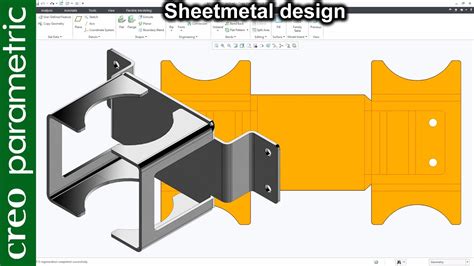
Check out this video on Creo Sheetmetal Design from PTC Application Engineers. Presenters: Lino Tozzi (Technical Specialist, Fellow) and Ryan Butcher (Technical Specialist, Fellow) Original Date Presented: January 11, 2022. To dive deeper into the subject, check out Sheetmetal Design. Unknown catalog request error. Beginning of dialog window. By enabling the sheet metal mode in Creo, you've essentially entered a specialized design environment tailored to the unique demands of sheet metal components. This mode equips you with the tools and capabilities needed to create, modify, and optimize sheet metal parts effectively.
1: Introduction to the Creo Parametric Sheetmetal Design Process. 2: Sheetmetal Model Fundamentals. 3: Creating Primary Sheetmetal Wall Features. 4: Creating Secondary Sheetmetal Wall Features. 5: Bending and Unbending Sheetmetal Models. 6: Modifying Sheetmetal Models. 7: Sheetmetal Setup and Tools. 8: Detailing Sheetmetal DesignsSheetmetal Design using Creo Parametric is a comprehensive training course that teaches you how to create sheet-metal parts in Creo Parametric. The course builds upon the basic lessons you learned in Introduction to Creo Parametric and serves as the second stage of learning.Creo Elements/Direct Sheet Metal can generate an accurate 2D drawing of a flattened (unfolded) sheet metal part. With a single command, Creo Elements/Direct Sheet Metal generates the flat directly from the 3D model.A sheet metal manufacturing process consists of the following basic steps: 1. Set up the manufacturing database. It may contain such items as workcells (machine tools) available, tooling, site parameters, etc.
creo sheet metal tutorial pdf
Creo Elements/Direct Sheet Metal creates a new 3D sheet metal part. Options specific to Solid include: • Cut replaces an existing bend edge by a cut edge and divides the selected part into two parts.You can create sheet metal parts in one of the following ways: • Sheetmetal Mode—Using a specialized sheet metal environment • Assembly Mode—Using a top-down approach.

In this tutorial, you will learn a step-by-step approach to designing a sheet metal part in Creo Parametric. The tutorial covers the planar wall, extrude wall, flat wall, and flange wall.This Video explains basic sheet metal modeling in creo. Process of creating the basic features of sheet metal like bend, flange, cut, punch, wall creating, b. Check out this video on Creo Sheetmetal Design from PTC Application Engineers. Presenters: Lino Tozzi (Technical Specialist, Fellow) and Ryan Butcher (Technical Specialist, Fellow) Original Date Presented: January 11, 2022. To dive deeper into the subject, check out Sheetmetal Design. Unknown catalog request error. Beginning of dialog window. By enabling the sheet metal mode in Creo, you've essentially entered a specialized design environment tailored to the unique demands of sheet metal components. This mode equips you with the tools and capabilities needed to create, modify, and optimize sheet metal parts effectively.
1: Introduction to the Creo Parametric Sheetmetal Design Process. 2: Sheetmetal Model Fundamentals. 3: Creating Primary Sheetmetal Wall Features. 4: Creating Secondary Sheetmetal Wall Features. 5: Bending and Unbending Sheetmetal Models. 6: Modifying Sheetmetal Models. 7: Sheetmetal Setup and Tools. 8: Detailing Sheetmetal DesignsSheetmetal Design using Creo Parametric is a comprehensive training course that teaches you how to create sheet-metal parts in Creo Parametric. The course builds upon the basic lessons you learned in Introduction to Creo Parametric and serves as the second stage of learning.
corrugated sheet metal tulsa
corrugated metal house images
The initial appeal is to the local authority. If they reject it, you are then able to appeal to the independent adjudicator. If you have appealed within 14 days, the authority has rejected it, and you then wish to appeal to the adjudicator, you will lose the opportunity to pay the discounted rate.
creo sheet metal process|creo sheet metal basics